 |
Vittore Cossalter |
 |
Vittore Cossalter |
The importance of motorcycle braking could be represented by the words " first learn to brake... then ride".
Braking distance judgment and maximum braking performance capability are skills required for a safe ride in all road conditions.
Rider misuse of the brakes, especially of the rear one,is a reason of accident.
Instead, the proper use of the rear brake gives a useful contribute:
- in the braking phase approaching a turn;
- achieving maximum braking, fully applying both front and rear brakes without locking either wheel.
Contribute of the rear brake approaching a turn
Approaching a turn, the rear brake contributes to the motorcycle directional stability.
Dangerous situation could occur due to suddenly brake the front wheel; rear-wheel lock and skid occur when the weight of the motorcycle and rider is transferred away from the rear wheel and to the front.
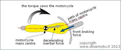
The front braking and the inertial forces generate a torque that yaws the motorcycle, towards the turn center.

Figure 1. Motorcycle turning with only the front braking force
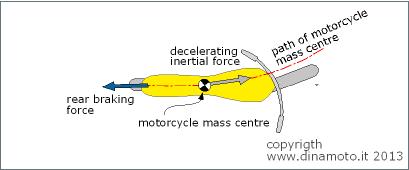
The braking force of the rearwheel has instead a stabilizing action on the directionality of the motion, as shown in Figure 2.

Figure 2 Motorcycle turning with only rear braking force
The above considerations suggest to utilize, during the turn approaching phase both the brakes.
Load transfer during the braking
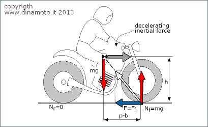
During the deceleration phase, the load on the front wheel increases, while the load on the rear wheel decreases, due to the load transfer.
The cardinal equations, applied to the entire vehicle, allow to calculate the wheels dynamic load and the transferred load.

Figure 3 Motorcycle in braking phase
Equilibrium of the horizontal forces
The deceleration inertial force (equal to the product of the mass m with the deceleration d) is equivalent to the sum of the braking forces:
Equilibrium of the vertical forces
the weight force mg is equal to the sum of the wheels vertical loads:
![]()
Equilibrium of moments around the mass center
![]()
where with F (force of total braking) is indicated the sum of the front braking force Ff and of the rear braking force Fr.
The dynamic load on the front wheel is equal to the sum of the static load and of the load transfer:
![]()
while the dynamic load on the rear wheel is equal to the difference between the static load and the load transfer:
![]()
The load transfer Fh/p is proportional to the total braking force, to the height of the center of gravity and inversely proportional to the wheelbase.
Assuming the braking force equal to zero, the wheels static vertical loads are found; these are function of the horizontal position of the gravity center.
| static load of the front wheel: | |
| static load of the rear wheel: |
In order to avoid tire skidding during the braking phase, the braking force must not exceed the product of the tire dynamic load and of the relative adherence coefficient. This product is the maximum applicable braking force to the tire in adherence limit condition.
Assuming ff and fr, the adherence coefficients respectively of the front wheel and the rear wheel, the total braking force in the adherence limit condition is given by:
![]()
If in the braking phase adherence limit condition is not reached, the braking force depends only from the coefficients of friction (indicated with m ) from front and rear wheels.
![]()
Figure 4 shows the dynamic loads on the wheels as function of the braking force. The loads on the wheels and the braking force, are presented in adimensional form, respect to the weight force. The vehicle has a static load radio on the two wheels equal to 50:50; the center of gravity is at equal distance from the wheels.
If the adherence coefficient is low, for example equal to f = 0.2 for both the wheels, the dynamic loads are 0.4 on the rear wheel and 0.6 on the front. In these conditions, the misuse of the rear brake reduces the braking force of40%..
Figura 4. Adimensional dynamic loads on the wheels versus the ratio of the braking force with the weight force
The figure 4 shows that with an adherence coefficient equal to f = 0.9, the braking ratio at the front wheel is equal to 0.95 while is equal to 0.05 at the rear wheel. The contribute of the rear braking force is negligible indeed.
The rear brake importance is negligible on optimal road surface with high adherence coefficient, but becomes important in slippery condition.
Forward motorcycle tilting
Previous figure shows that during the deceleration phase, the load on the front wheel increases, while the load on the rear wheel decreases, due to the load transfer.
If the rear wheel load is zero, the dynamic load on the front tire is equal to the motorcycle weigh. The action line of the dynamic load and of the braking force passes through the center of gravity.
The braking force in forward tilting condition is:
![]()
The smaller is the force, the easier it is to tilt the motorcycle.
If the braking force is constant, the tilting condition is function of the position of the center of gravity and of the mass of the vehicle..
The forward tilting deceleration is:
![]()
The value found above is a function of the center of gravity position, not of the mass of the motorcycle.
In order to increase the maximum forward tilting deceleration, the center of gravity must be as low and backward as possible.

Figura 5 Motorcycle in forward tilting condition
The optimal braking
The optimal braking allows to achieve the maximum deceleration, that is:
![]()
The deceleration is a function of the wheelbase p, of the vertical h and horizontal position of the center of gravity and of the coefficients of friction, not of the vehicle mass. The ratio between the front wheel braking force and the total available braking force depends only from the geometrical properties and the coefficients of friction:
![]()
Figure 6. Deceleration lines and braking ratio
wheelbase p=1.4 m; height of the center of gravity h=0.7 m; horizontal position of the c.o.g. b=0.7 m
The above figure shows that the deceleration increases with the coefficients of friction. Due to the load transfer the front wheel braking force is bigger than the rear wheel braking force.
The braking ratio between the front and the rear wheel are expressed by the red lines.
The horizontal axis represents a rear wheel only braking condition; the vertical axis a front wheel only braking condition.
If the coefficients of friction are low, the importance of the rear braking force is not negligible, as in high friction condition.
The maximum deceleration before the forward tilting is 1 g.
As an example consider braking a vehicle with a deceleration equal to 0.5g; it is possible to reach the desiderate decelerationusing different ratio braking. Braking using the front wheel only, requires a front coefficient of friction equal to 0.68 (point A).
If the used braking ratio is 80% on the front wheel, 20% on the rear wheel, the same 0.5g deceleration requires a front coefficient of friction equal to 0.55 and equal to 0.4 on the rear wheel (point B).
Which is then the optimum braking to achieve the 0.5g deceleration?
If the maximum coefficients of friction are the same for both the wheels, Figure 7 shows that the maximum deceleration is achieved when both the tires are used in the same way.
As an example consider a coefficient of friction equal to 0.8 for both the tires; the maximum deceleration (0.8g) is achieved with a braking ratio equal to 90:10.
Using the front brake only, the maximum deceleration is equal to 0.67g; using only the rear brake is equal to 0.29g.
In slipping condition the coefficient of friction is equal to 0.4, the maximum deceleration is equal to 0.4g and the optimum braking ratio is 30:70.
Se il fondo stradale è più scivoloso e i coefficienti di aderenza di entrambe le ruote risultano pari a 0.4 la frenata ottimale si ha con una diversa ripartizione (30/70) e fornisce una decelerazione pari a 0.4 g.
The 45° line represents the condition mf= mr and is the optimum braking; this line intersects different braking ratio lines as function of the desiderated deceleration.
Figure 7. Braking action of dry(0.8) and wet(0.4) surfaces
Figure 8 shows that the optimum braking line is tangent to the 50:50 braking ratio; it do not intersect the ration curves with the rear wheel braking force bigger than the front wheel braking force.
The above consideration is valid even if the static load is bigger on the rear wheel.
The optimum braking line is always tangent to the ratio curve having the same values of the static loads ratio.
As an example, if the static loads ratio is 45:55 (45% on the front wheel, 55% on the rear wheel), the optimum ratio curve is the 45:55 and is tangent in the origin to the optimum braking line.
Figura 8. Braking action of dry(0.8) and wet(0.4) surfaces
wheelbase p=1.4 m; height of the center of gravity h=0.7 m; horizontal position of the c.o.g. b=0.7 m
-